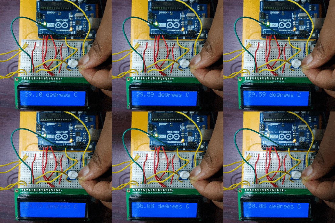
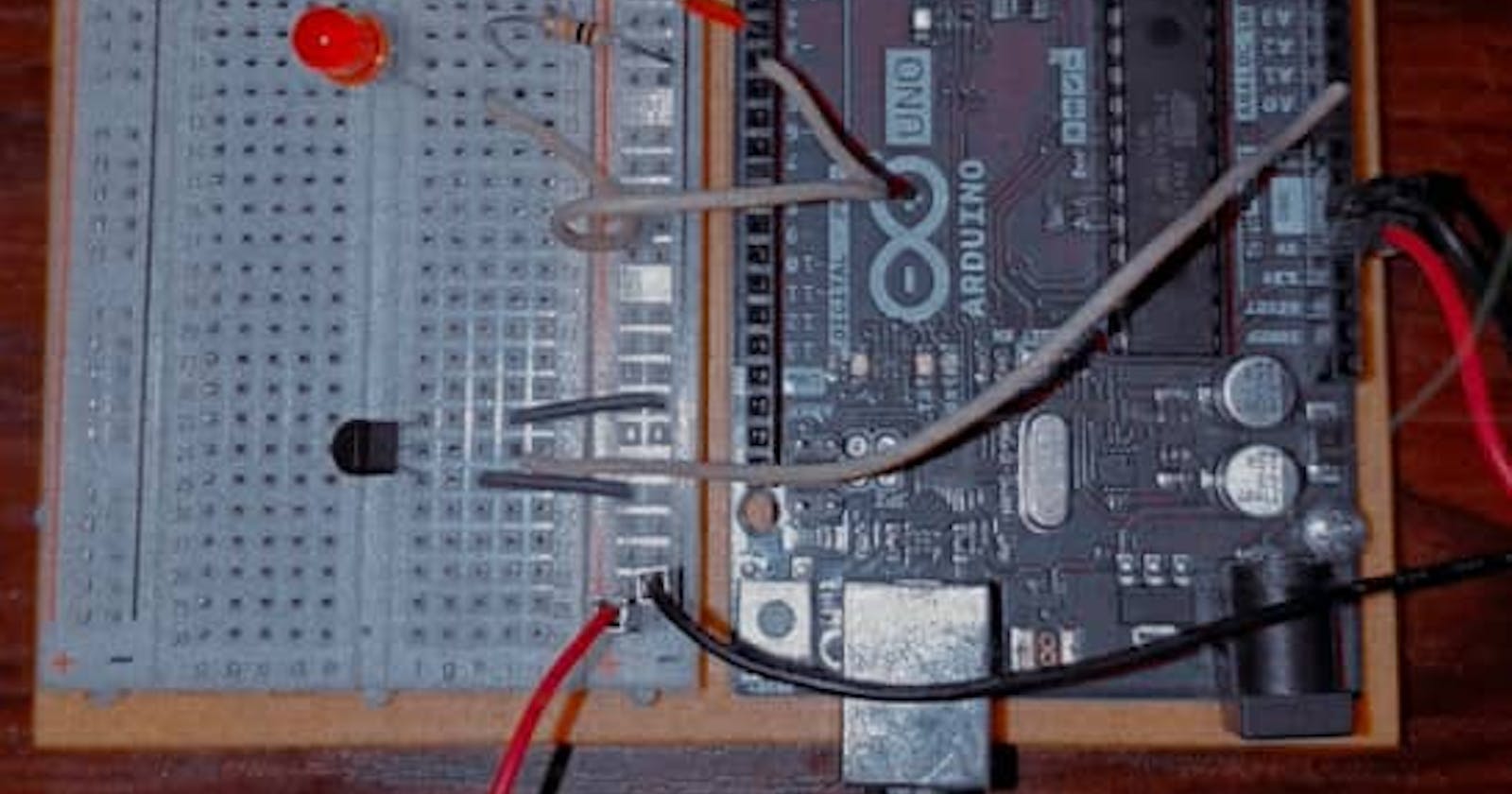
In project 02, we wrote our first lines of Arduino code. In this project, we will not only be writing code, but we will also work with our first sensor, the temperature sensor.
Requirements
- Three red LEDs
- Three 220 ohm resistors
- Temperature sensor
- Jumper wires
The project description as written in the project's book;
You'll be using a temperature sensor to measure how warm your skin is. This component outputs a changing voltage depending on the temperature it senses. It has three pins: one that connects to the ground, another that connects to power, and a third that outputs a variable voltage to your Arduino. In the sketch for this project, you'll read the sensor's output and use it to turn LEDs on and off, indicating how warm you are. There are several different models of temperature sensors. This model, the TMP36, is convenient because it outputs a voltage that changes directly proportional to the temperature in degrees Celsius.
The Arduino software (IDE) comes with a serial monitor tool that enables you to report back results from the microcontroller. Using the serial monitor, you can get information about the status of the sensors and get an idea about what is happening in your circuit and code as it runs.
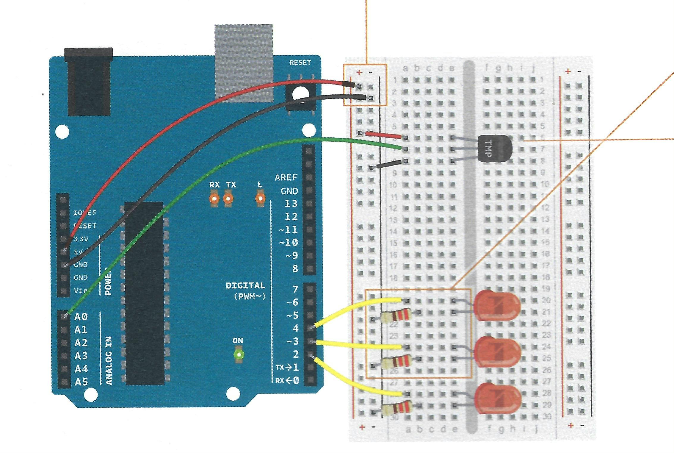
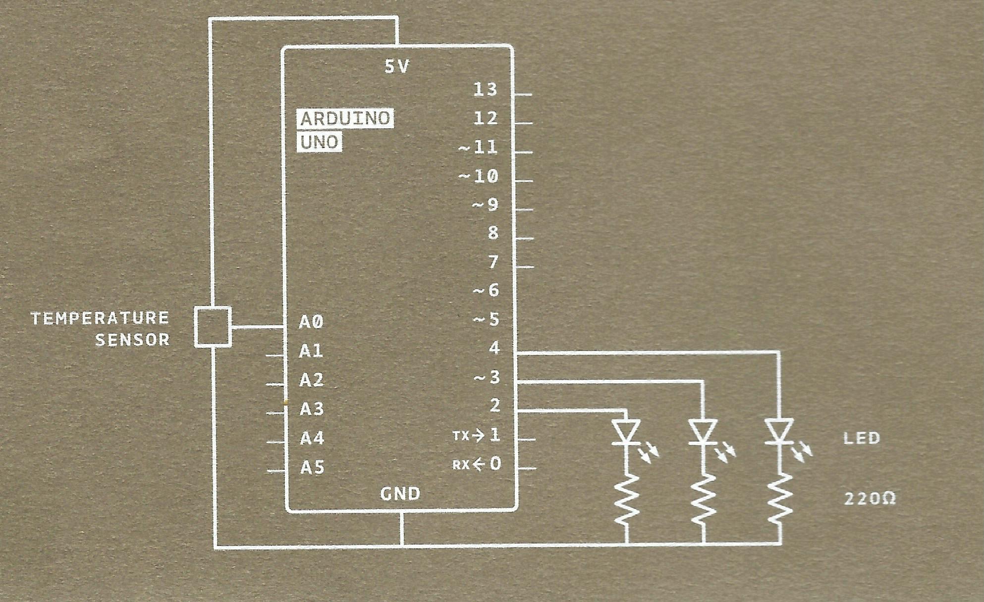
The breadboard and circuit schematics as drawn in the project's book;
The Code
We covered the structure of Arduino code in project 02, where we talked about the setup() and the loop() functions. We also dealt with variables and digital pins. In this project, in addition, we will be dealing with analog pins and constants.
Analog systems, unlike digital systems, which transmit information in either 0 or 1 format, transmit the information as electric pulses of different amplitude. The Arduino has a built-in Analog-to-Digital Converter (ADC). Analog pins A0-A5 have values that range from 0-1023 Constants are different from variables in the sense that they cannot change.
Let's run through the code below.
- We start by defining our constants. The sensorPin is the analog pin on which the sensor is connected. The baselineTemp is the temperature in your current environment. If you have no means of measuring the temperature, let's give it the default value for room temperature, 25 degrees Celsius.
- In the
setup(), we useSerial.begin()to allow the Arduino to send messages via the Serial monitor. It takes two argumentsSerial.begin(speed, config), the latter is optional. In this case, we're telling the Arduino to communicate at a rate of 9600 bits per second. - We use a
for()loop to set the pins we connected to the LEDs, unlike project 02, where we defined each pin one after the other, here we set everything in the loop LOW, pin 2 to 4. - In the
loop(), we defined a variable sensorVal which stores the value of the sensorPin, which is our analog pin. Then, we useanalogRead()to get the value from the analog pin. Serial.print()displays human-readable data on the serial monitor. It can display the value of a variable or of anything you type in quotation marks.- Here's a formula for converting ADC reading to voltage.

In this case, we're looking for the voltage value, making that the subject of the formula, we store the value in the variable named voltage. Then we print it out to the serial monitor.
- We then convert the voltage to temperature(Celsius) using the formula "(voltage - .5) * 100", then we print this value to the serial monitor using the
Serial.println()this is different from theSerial.print()as it creates a new line. - We then use the temperature to set up our if and else statements. If the temperature is less than our baselineTemp incremented by 2, we set all three LEDs off. Then, we start turning each LED on as the temperature rises.
- We set a delay so we can easily read the values on the serial monitor.
The code as written in the project's book:
const int sensorPin = A0;
const float baselineTemp = 25.00;
void setup() {
  // put your setup code here, to run once:
  Serial.begin(9600);
  for(int pinNumber=2; pinNumber <5; pinNumber++){
    pinMode(pinNumber, OUTPUT);
    digitalWrite(pinNumber, LOW);
  }
}

void loop() {
  // put your main code here, to run repeatedly:
  int sensorVal = analogRead(sensorPin);
  Serial.print("Sensor Value: ");
  Serial.print(sensorVal);

  // convert ADC reading to Voltage
  float voltage = (sensorVal/1024.0) * 5.0;
  Serial.print(", Volts: ");
  Serial.print(voltage);
  Serial.print(", degrees C: ");

  // convert the voltage to temperature in degrees
  float temperature = (voltage - 0.5) * 100;
  Serial.println(temperature);
  if(temperature < baselineTemp+2){
    digitalWrite(2, LOW);
    digitalWrite(3, LOW);
    digitalWrite(4, LOW);
  }
  else if(temperature >= baselineTemp+2 && temperature < baselineTemp+4){
    digitalWrite(2, HIGH);
    digitalWrite(3, LOW);
    digitalWrite(4, LOW);
  }
  else if(temperature >= baselineTemp+4 && temperature < baselineTemp+6){
    digitalWrite(2, HIGH);
    digitalWrite(3, HIGH);
    digitalWrite(4, LOW);
  }
  else if(temperature >= baselineTemp+6){
    digitalWrite(2, HIGH);
    digitalWrite(3, HIGH);
    digitalWrite(4, HIGH);}
  delay(1);
}
The steps to upload the program to your board;
- Save the sketch
From the menubar, click tools;
- Make sure you have the right board selected
- Select a port
- Set the programmer to ArduinoISP
- The upload button is the right arrow.
Let's check out the Serial monitor:

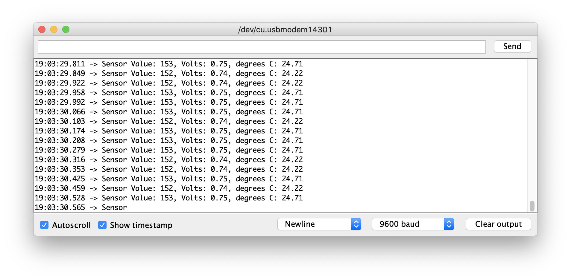
If you weren't sure of your baselineTemp before you touch the sensor, the temperature reading is that of your environment, and you can update your baselineTemp and upload the code again.
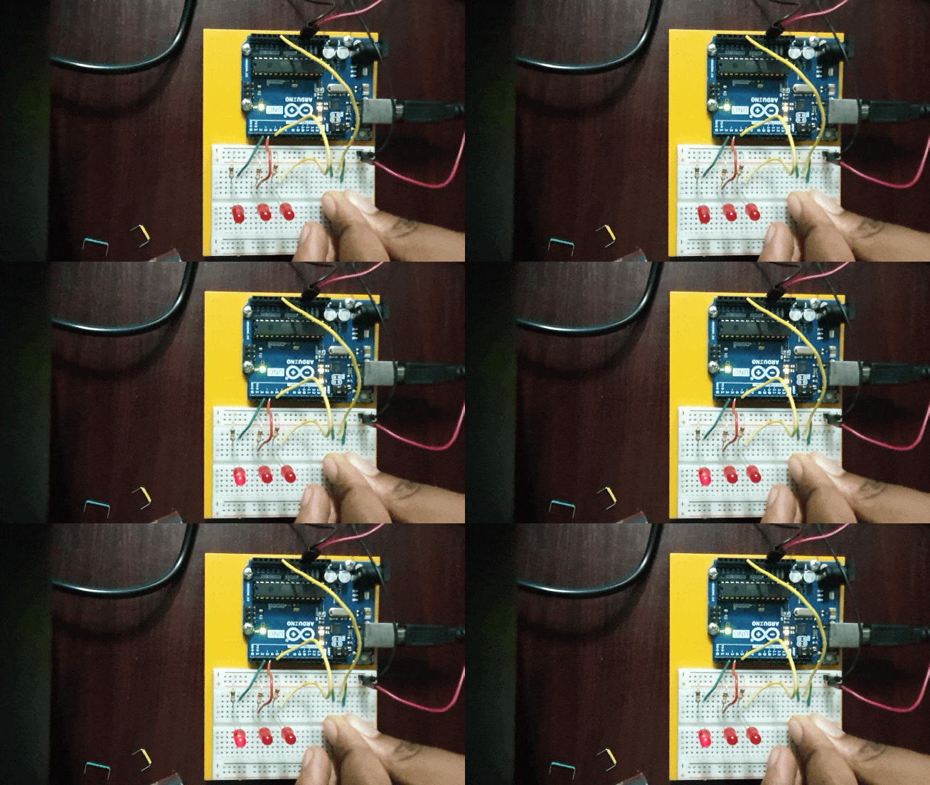
Your body temperature is always higher than your environment; if you hold the sensor for a while, one or more LEDs should light up.
My body temperature was hot enough to make one LED light up.
Using LCD
I decided to use a 16x2 LCD to display the temperature and a Potentiometer to control the contrast on the LCD screen.
Requirements
- One potentiometer (optional)
- One 220 ohm resistor
- Temperature sensor
- 16x2 LCD
- Jumper wires
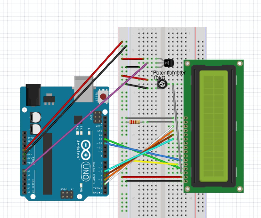
Schematics
Something to note: The LCD is labeled from 1 to 16. In this diagram, one is at the bottom and 16 at the top.
The Code
Let's jump into the differences here.
- Here, we import the LiquidCrystal library and initialize it by telling it what pins to use to communicate. We don't need the baselineTemp here.
- We use the
lcd.print()to display content to the LCD screen. It works the same way asSerial.print(); the difference is that we're displaying to the LCD and the Serial Monitor, respectively. - Then, we delay for 2 seconds to keep the LCD from flashing the values the way the values flash in the Serial Monitor. Finally, we use the
lcd.clear()so that each value stands alone on the screen.
#include <LiquidCrystal.h>
LiquidCrystal lcd(12,11,5,4,3,2);
const int sensorPin = A0;
void setup() {
  // put your setup code here, to run once:
  Serial.begin(9600);
  lcd.begin(16,2);
  }

void loop() {
  // put your main code here, to run repeatedly:
  int sensorVal = analogRead(sensorPin);
  Serial.print("Sensor Value: ");
  Serial.print(sensorVal);

  float voltage = (sensorVal/1024.0) * 5.0;
  Serial.print(", Volts: ");
  Serial.print(voltage);
  Serial.print(", degrees C: ");

  float temperature = (voltage - .5) * 100;
  Serial.println(temperature);

  lcd.print(temperature);
  lcd.print(" degrees C");
  delay(2000); //two seconds delay

  lcd.clear();
  delay(50);
}
After uploading your program, the temperature you see on display is the temperature of the environment. Place your finger over the sensor and observe the changes in the temperature values displayed on the screen.
