I was super excited to receive my Arduino starter kit (I call it ASKit) and Engineering kit from the official Arduino store. I jumped straight into exploring the components in the Arduino starter kit, I'm yet to open the engineering kit. It came with a cool projects book and in this article I'll be sharing a few things about project 01 which covered turning LEDs on.
The Arduino starter kit came with the Arduino Uno, a breadboard, a base and loads of other cool components. I particularly love the breadboard as it means no soldering and all components are reusable and the circuit is temporary.
Requirements
- 220 ohm Resistor
- LED
- Two push button switches
- 5V power supply
Without a push button.
Here's the schematic circuit diagram below;
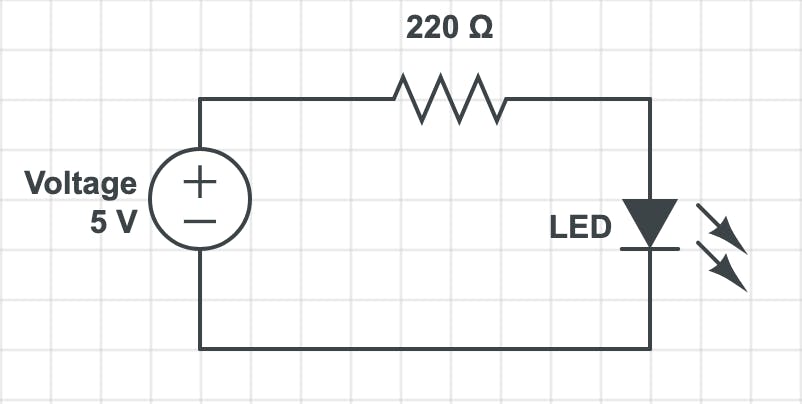
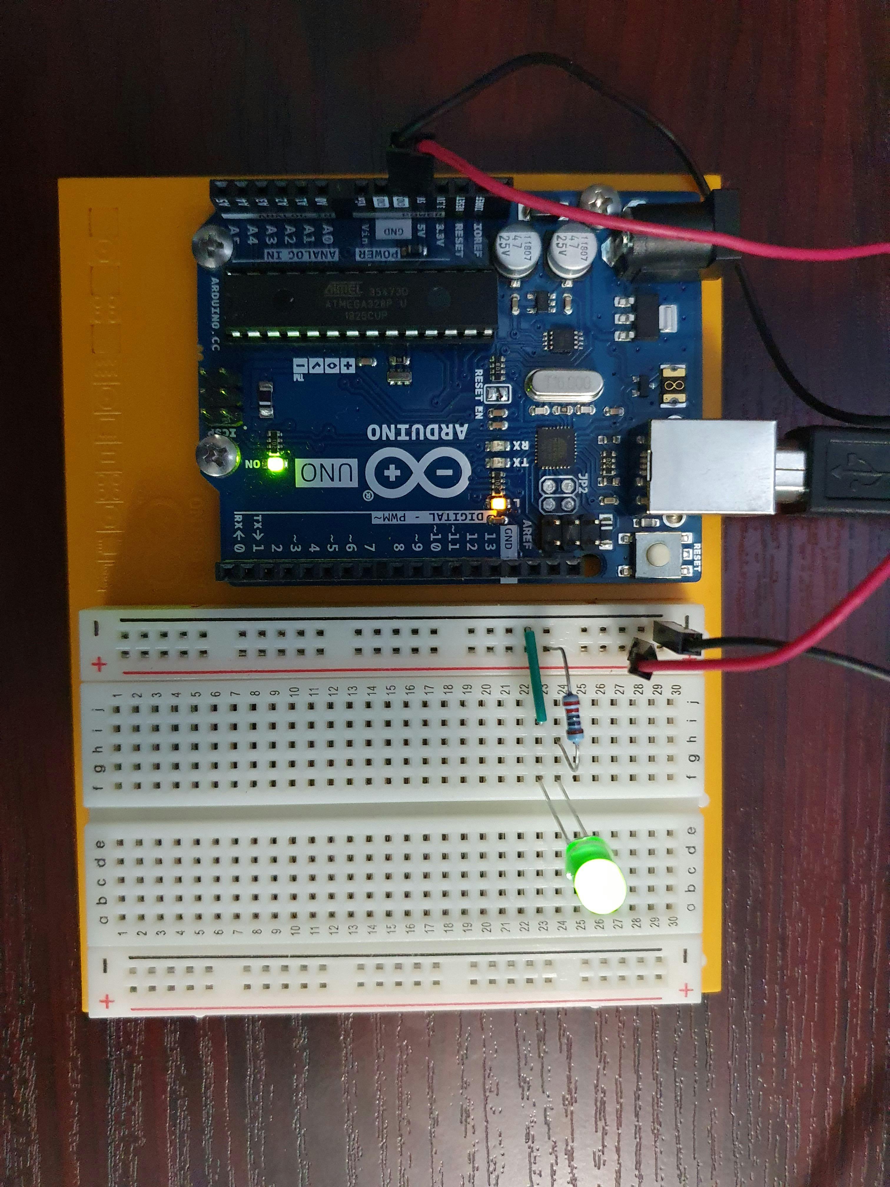
The Uno has a 5V power supply pin and a 3.3V pin, I used the 5V power supply pin and connected the Uno to my laptop with a cable. The longer leg of the LED is the anode (+end) and the shorter leg is the cathode (-end).
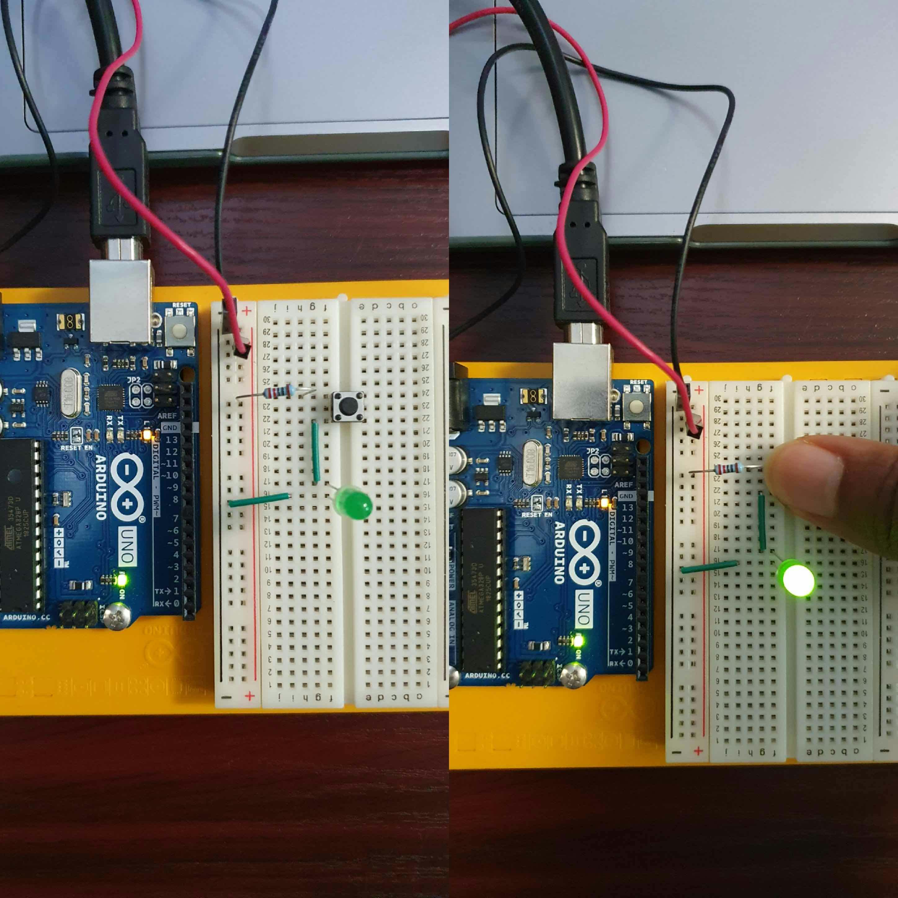
Here's how it looks;
With one push button.
Here's the schematic circuit diagram below;
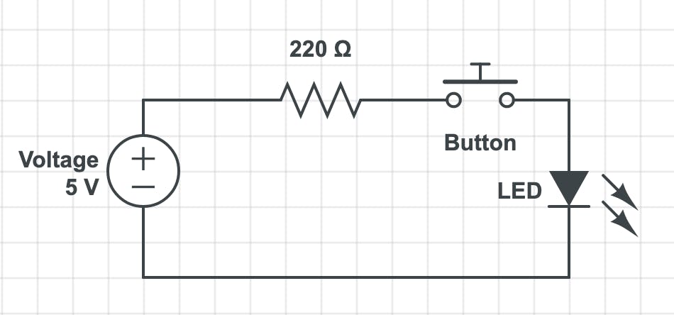
Note: The button is placed at the center of the breadboard with one part at the other side of the ravine to keep the horizontal part on the same row.
On the left hand side the button hasn't been pressed hence the LED is still off, and on the right hand side the button is pressed, so the LED is on.
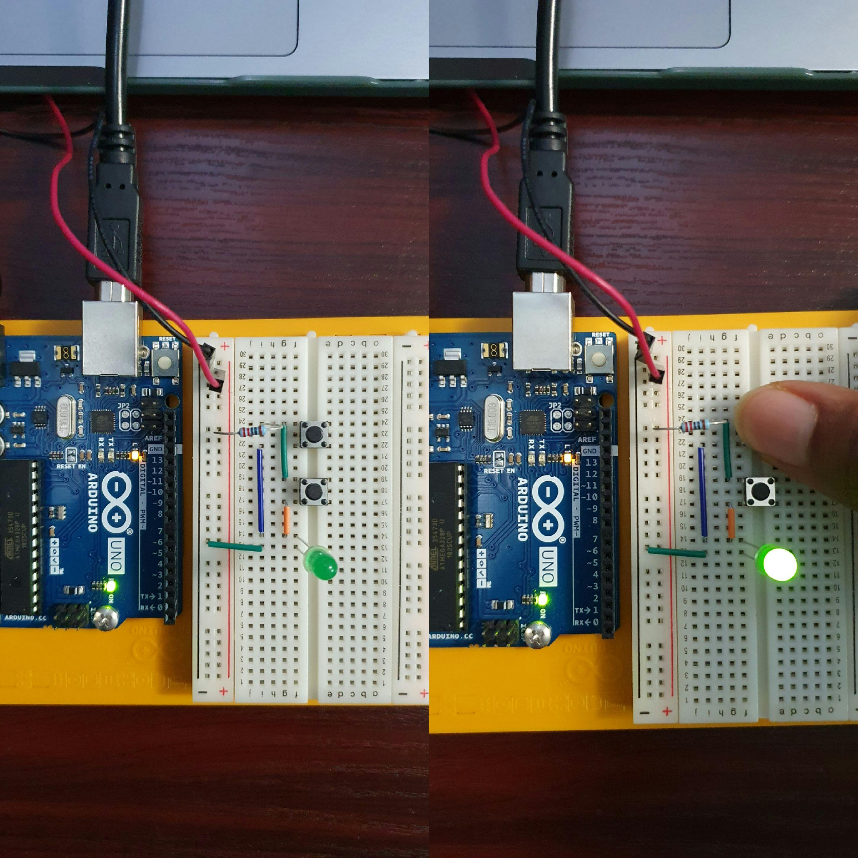
With two push buttons, serial circuit.
Here's the schematic circuit diagram below;
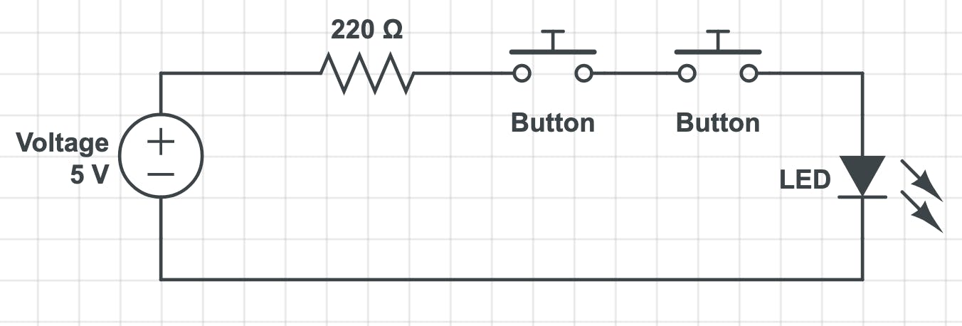
On the left hand side no button is pressed hence the LED is off. On the right hand side both buttons have to be pressed for the LED to come on because they're connected in series and the same current flows through them.
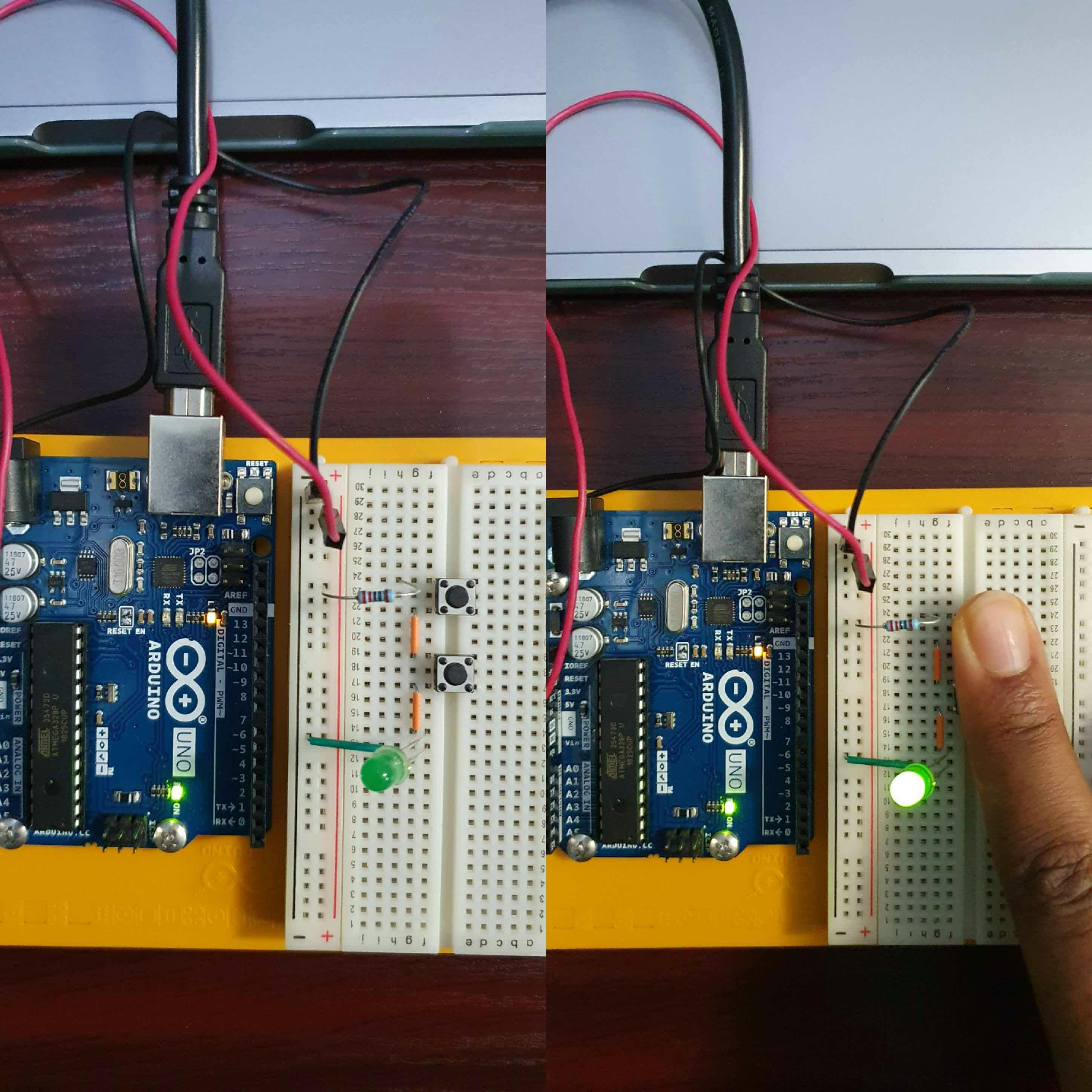
With two push buttons, parallel circuit.
Here's the schematic circuit diagram below;
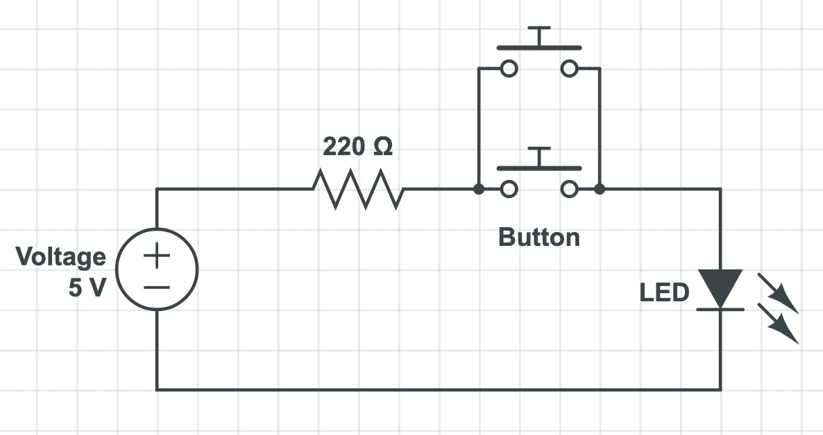
On the left hand side no button is pressed hence the LED is off. On the right hand either button can be pressed for the LED to come on because they're connected in parallel and the current is split between both of them.
One exciting part of junior secondary school was learning about Ohms law in Integrated Science class which states that:
The current through a conductor between two points is directly proportional to the voltage across the two points.
Hence V = IR, using ohms law to calculate the current passing through the LED, where V = 5 and R = 220, we have approximately 0.02 amps. We used the 220 ohm resistor because 0.02 amps is just about the maximum current for common LEDs.
When you explore further, note;
- Always turn off your power supply before making connections.
- If you want to use two LEDs do not connect them in parallel to one resistor.
References:
- Arduino Projects Book

